Zane Golas
Purpose
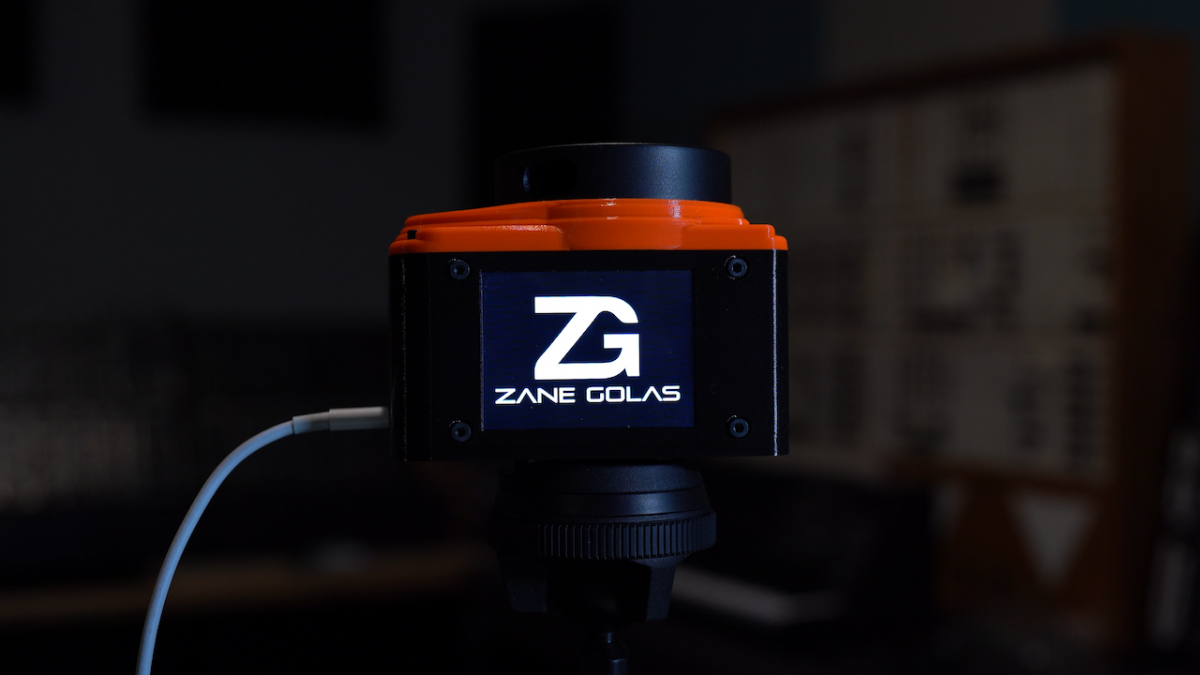
This device tracks objects within a given range and translates their position over time into midi data for use with any device that accepts USB Midi. It is easily reproducable with 3D printing and commonly available parts. The device is designed to run without any reprogramming by the end user, but the open source nature allows for deep customization if you so choose.
https://github.com/zanegolas/Interface_Design
Applications
- Parameter modulation based on how members of a band move around on stage
- Allowing dancers to play chords and notes based on their choreography without needing to wear sensors
- Control of the sound in an art installation based on audience movement
- Audience feedback that can control an aspect of the overall performance sound
Fabrication
Required Parts
- Teensy 4.1
- Ordering the TEENSY41_PINS version is easiest but you can solder your own pins if you prefer
- Parts From Amazon
- BOM From Digikey
- You can switch out the types of connectors and wires here
I will list the McMaster-Carr parts out in a table by individual pieces, as they may be easy to substitute with something you have on hand, and ordering packs of 50-100 just for this project could quickly double the budget.
Quantity Part # Description 4 98952A106 Aluminum Male-Female Threaded Hex Standoff, 4.5mm Hex, 8mm Long, M3 x 0.50 Mm Thread 4 91290A113 Alloy Steel Socket Head Screw, Black-Oxide, M3 x 0.5 Mm Thread, 8 Mm Long 6 91290A111 Alloy Steel Socket Head Screw, Black-Oxide, M3 x 0.5 Mm Thread, 6 Mm Long 3 91290A572 Alloy Steel Socket Head Screw, Black-Oxide, M3 x 0.5 Mm Thread, 15 Mm Long 1 90611A112 Screw-Mount Nut, Steel, 1/4"-20 Thread, 0.313" Diameter x 1/4" High Barrel 13 97258A101 18-8 Stainless Steel Thin Square Nut, M3 x 0.5 Mm Thread 7 91290A102 Alloy Steel Socket Head Screw, Black-Oxide, M2.5 x 0.45 Mm Thread, 8 Mm Long 7 90710A025 18-8 Stainless Steel Thin Hex Nut, M2.5 x 0.45 Mm Thread, Din 439B, Iso 4035 3D Printing
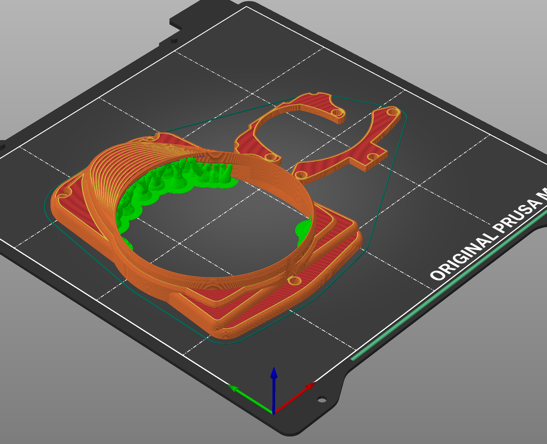
The enclosure is printed in PETG for better durability and resiliance to heat. I printed using a Prusa Mini+ and and Prusament. The GCode for that combination is included in this repository, along with .3mf files which contain prusa slicer projects that you can customize to your needs. Please be aware that in order to acheive a clean look, the print is set to pause whenever a square nut needs to be inserted in the body. If you tweek the settings those pause points will likely be inaccurate so you will need to reset them. I'll post further documentation on that process in the 3D_Print folder. For now you will just find two sets of files, as the print is split between top and bottom.

It is also important to note that there is a long thin bridge where the top of the LCD screen sits, and the best way I found to get it to print was using the organic supports which are only in the alpha build of PrusaSlicer at the moment.
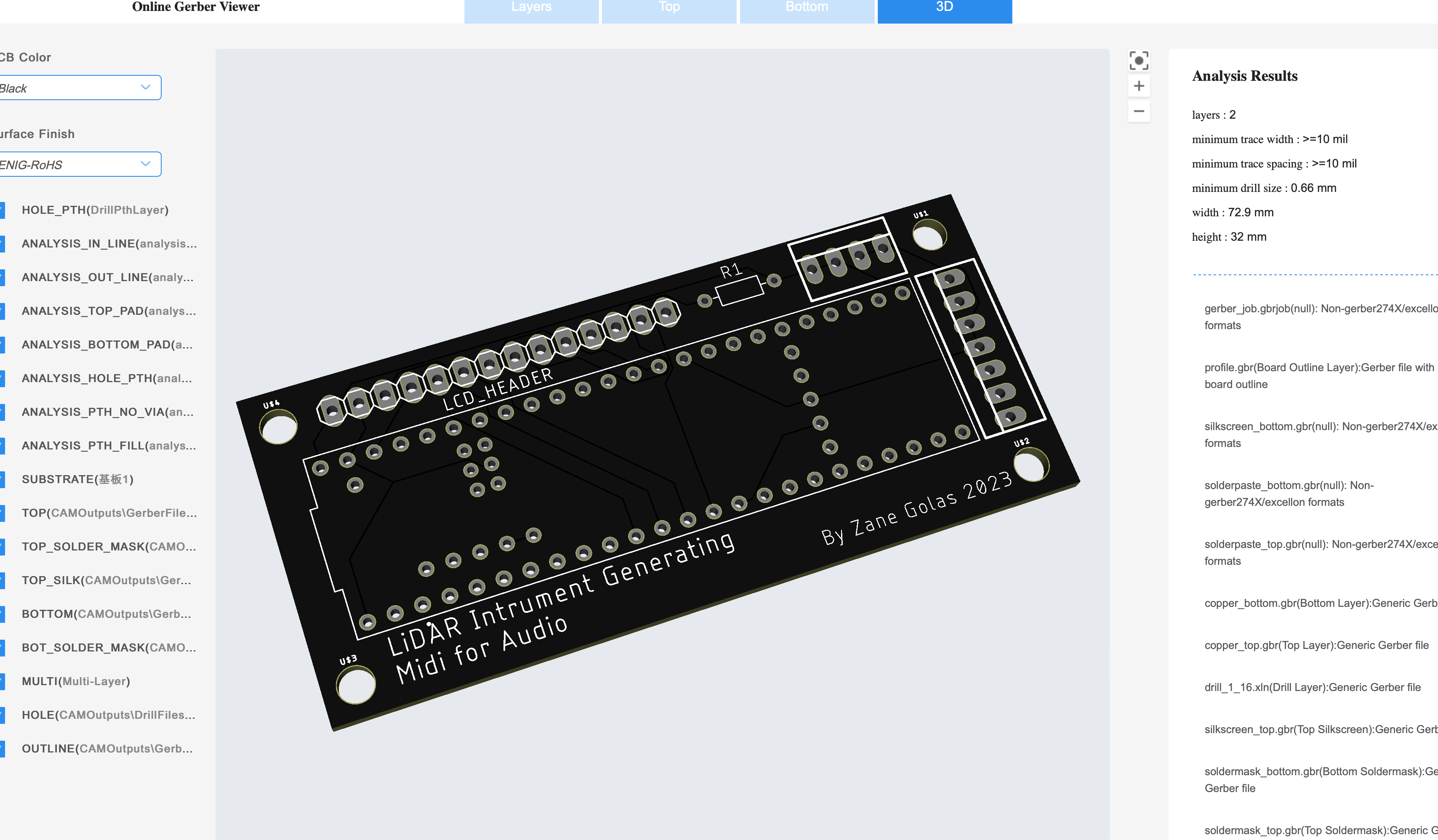
Custom PCB
This is more of a breakout board than anything, and is at the top of my priority list for a revision as I'd like to make the internal usb connection cleaner and add the ability to use some better libraries to drive the screen. It is fairly cheap to manufacter through a company like JLCPCB and I have included the gerber files in the PCB folder. Simply upload them to the website and pick what color you want the board to be.
Soldering
I will expand on this section in the comming weeks but the main soldering can be broken down into 4 groups:
- Cut micro usb cable soldered to usb c breakout board
- Soldering all the pins to the custom PCB
- Desoldering the header pins that came with the LCD and soldering the molex connector on (this can be skipped if you aren't concerned about cables coming loose inside)
- Cutting the default RPLiDAR cable and resoldering it to the right wire gauge/connector for your board
Software
Building and Installing
This project uses Platform.IO and CLion, though VSCode shouldn't be an issue. The most important thing is just to make sure platform.io is installed and configured correctly, then you should be able to clone the repository and your IDE will do the rest of the work. I will also put compiled versions in the release area incase you just want to use teensy loader to flash the device without changing the code.
Code Organization
- ZGLidar : Handles management of the physical lidar device and pulling data off the serial buffer.
- ZGObjectTracker : This analyzes point cloud data from the lidar and attempts to match objects positions over time. Holds all tracked objects and tells them when they are no longer relevant
- ZGObject : Represents a tracked point and manages all midi updates and signals throughout it's lifetime. It only reuires updated coordinates to derive further parameters that it needs to send
- ZGDisplay : This manages the realtime data display and touch screen menu
- ZGConversionHelpers : Inline functions that are useful in multiple objects
Touch Screen Options
- Gear Icon : Brings up the main menu
- SCAN : Contains settings related to LiDAR data processing
- Range - Sets the maximum detection distance for object tracking
- Algorithm - Switches between Distance (Low Latency/Low Accuracy) and DBSCAN (High Accuracy/10-20ms added latency)
- MIDI : Contains settings that modify the Midi being sent as a result of processing the data
- Root Note - Sets the note that will be assigned to the 0 degree position
- Scale Type - Changes the number of notes in a 360 degree pattern and the offset for each degree to quantize to a scale mode
- DISPLAY : Contains settings that modify the information displayed during realtime updates
- Main View - Allows user to select between a plot of tracked points and a debug screen outputting latency measurements
- ABOUT : Contains info about the project and current version
- SCAN : Contains settings related to LiDAR data processing
- Teensy 4.1